- Arduino
- 16×2 LCD Display
- 220 ohm resistor
- Breadboard
- 10k ohm variable resistor
- 14 connecting wires
In order for us to display information from the Arduino we need to connect some form of display. If this is to be a small amount of readable text then a sixteen character, two line (16×2) display can work well. We’ll need to be able to send data to it but let’s start with some simple text. There is an example that comes with the Arduino IDE, so no need to install additional libraries. However the default Hello World example on the website here (https://www.arduino.cc/en/Tutorial/HelloWorld) didn’t work for me. So we’ll go through it and then ‘debug’ the problem and fix it.
The display we have chosen for this example is based on the Hitach HD44780 chipset, which will very likely not mean anything to you at this point. However what it does mean is that it is compatible with the Liquid Crystal display example in the Arduino IDE. So, following our usual methodology we can reuse what some generous people have already built for us and go further faster.
First open the Hello World example. Click File->Examples->Liquid Crystal->HelloWorld, this will open the example file. Then click File -> Save As and save a copy to your directory.
Plug the Arduino into your computer. Before we compile the code and upload it to the Arduino click the Tools menu option and check that the Board and Port are defined correctly, if not select the correct options for each. Then click the right arrow button to compile and upload the code. You will see the transmit(TX) and receive(RX) lights flash quickly on the Arduino board as the code is transferred. Once this completes the RX light will flash quickly.
Next we need to connect the Arduino to the display, and there are quite a few connections, but first unplug it from your PC. We load the code first so that the Arduino is in a known state, otherwise there is no telling what was running on there previously and it could affect our sensor.
Here is the wiring diagram (created in Fritzing):

It doesn’t matter which way around the resistor goes. For the variable resistor be sure to connect the centre leg to the fourth pin on the LCD and the other two to +5v and GND.
Please note that conventionally the Arduino pins are numbered starting from zero but the LCD is number starting from 1.
The connections are as follows:
| From | To |
|---|---|
| Arduino pin 2 | LCD pin 14 |
| Arduino pin 3 | LCD pin 13 |
| Arduino pin 4 | LCD pin 12 |
| Arduino pin 5 | LCD pin 11 |
| Arduino pin 11 | LCD pin 6 |
| Arduino pin 12 | LCD pin 4 |
| Arduino +5v | Breadboard positive rail |
| Arduino GND | Breadboard negative rail |
| LCD pin 1 | Breadboard negative rail |
| LCD pin 2 | Breadboard positive rail |
| LCD pin 3 | Centre leg of the variable resistor |
| LCD pin 5 | Breadboard negative rail |
| LCD pin 15 | Via a 220ohm resistor to breadboard positive rail |
| LCD pin 16 | Breadboard negative rail |
Then CHECK all of your connections.
Once you’re happy then connect your Arduino to your computer and the screen should light up. If you cannot see anything on the screen then turn the variable resistor until you can.
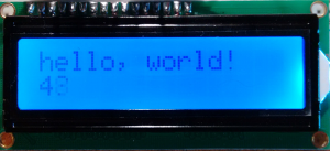
However on my screen this didn’t look right. I was expecting to see ‘Hello World’ on the first line and then an increasing number of seconds on the second as per the code in the example:
So, something was wrong. The first thing to consider is the connections as a loose one or incorrect one could cause the data being sent to the screen to be incorrect.
Next let’s actually look at the code.
// initialize the library with the numbers of the interface pins LiquidCrystal
lcd(12, 11, 5, 4, 3, 2);
As the comment says this should initialise the library with the pins we are using, and they match the connections. Then in the setup() function we set the number of rows and columns and send the text hello, world! to display on the screen.
// set up the LCD's number of columns and rows:
lcd.begin(16, 2);
// Print a message to the LCD.
lcd.print("hello, world!");
However that’s not happening, so maybe something after that is messing it up. The quickest and easiest way to check is to comment out the later code in the loop() function and then compile and upload it again as shown:
void loop() {
// set the cursor to column 0, line 1
// (note: line 1 is the second row, since counting begins with 0):
//lcd.setCursor(0, 1);
// print the number of seconds since reset:
//lcd.print(millis() / 1000);
}
This time when you upload the code hello, world! should be displayed.
In which case the problem must be with the code that we’ve just commented out, and it is. The first line we commented out sets the cursor position to the start of the second line (numbering starts at zero), so it’s unlikely to be that but then the second line prints the number of milliseconds since the Arduino started, divided by 1000 – so actually the number of seconds. However if we look at the print() function: https://www.arduino.cc/en/Reference/LiquidCrystalPrint
It tells us that the data passed to the function can be of one of 5 types:
data: the data to print (char, byte, int, long, or string)
When we divide by 1000 though we end up with a floating point value, i.e. a decimal, and that’s confusing things. Therefore we need to force it to be one of the types that is permitted. The easiest and most obvious in this case is an integer (int) as the number of seconds we only need as a whole number, no decimal places. So let’s modify the code to create an integer variable, store the value in that and then send that to the function, like this:
void loop() {
// set the cursor to column 0, line 1
// (note: line 1 is the second row, since counting begins with 0):
lcd.setCursor(0, 1);
int secs = millis() / 1000;
// print the number of seconds since reset:
lcd.print(secs);
}
Now when you compile and upload you should see the screen display functioning as expected.